Yet Another FSR Dance Pad Build Guide

Here's a little diary on how I made my dance pad using primarily plywood and FSRs.
But Why
I looked at many different DIY pad guides, and none of them balanced my priorities the way I hoped. Those priorities being:
- CHEAP I'm so broke help
- Low-profile for easier storage (I live in a small apartment)
- FSR sensors, not contact sensors
- Very little panel travel for a firm feel, like arcade pads
- All 9 panels mobile so I can upgrade it to 9 panel some day
- Materials available in Canada
Many things one can take for granted in the States are harder or more expensive to find in Canada. Case in point, I thought I was getting a deal buying my microcontroller of choice from DDRPad.com, an American store, because it was the cheapest option by far I could find compared to Canadian options. But I ate hella dirt on the import fees (read: raised the cost by 50%), making it far more expensive than any Canadian seller would've been. I walked so you could run (away), dear Canadian reader.
Let it be known that I have almost no prior woodworking or electronics experience (but I do have an electrical engineer father-in-law — I am fully-in-his debt). If JM from Website can do it, you can too, as long as you have access to some tools or fathers-in-law.
The Design
With these priorities, I designed, or at least amalgamated from other designs, the pad like so:
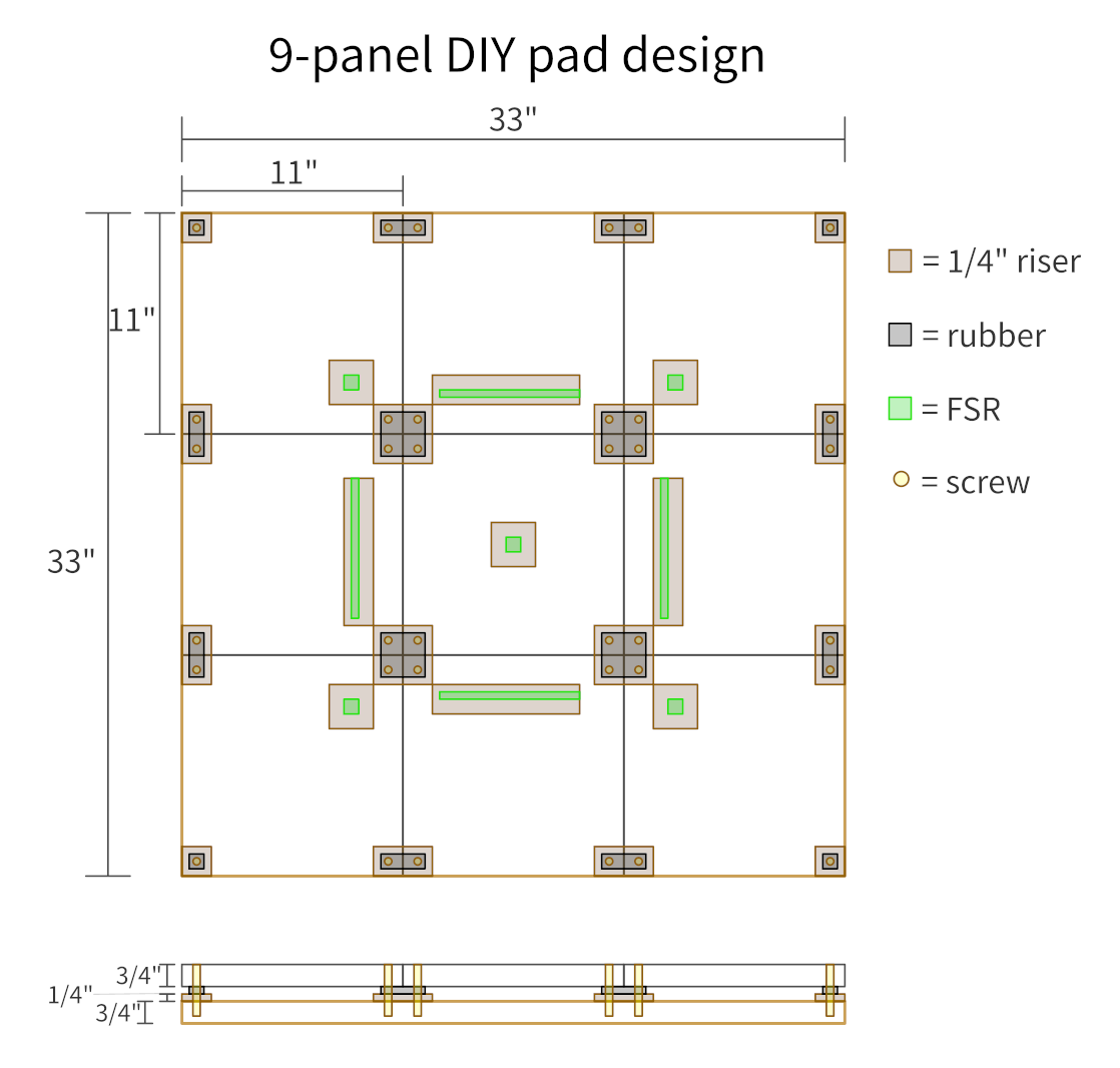
Despite the design incorporating 9 FSRs, I only bought and constructed for 4 FSRs for now. The rest of this guide will assume 4-panel.
Materials:
- 3/4" plywood base, measuring 33" x 33"
- 1/4" plywood strips for panel supports, roughly 1 1/2" squared each
- Rubber weather stripping on top of 1/4" supports
- 1/4" plywood strips for FSR mounts, about 8" x 1 1/2"
- Cardstock to raise FSR height
- Painter's tape to further raise FSR height
- 4x 200mm FSR 408s
- 9x 3/4" plywood panels, each measuring just under 11" squared (about 10 15/16")
- Box of 8 x 1 1/2" wood screws
- Control box
- Arduino Micro clone with USB from DDRPad.com
- Small breadboard
- 4x 470Ω resistors
- Lotsa solid core wire
- Nonslip floor protector pads
Given that the panels and all of the wiring were things I had on hand, I don't have a calculable final cost. If I had to buy those new, I'd estimate my total materials cost to be about CAD$200. Not bad considering [looks out the window]!
For the 3/4" wood, I bought some cheap pine (I think?) plywood at a local lumber store and used some leftover melamine boards from my father in law. I had the plywood store cut the base at 33"x33". I wouldn't recommend the melamine board, because it makes sanding unfun and I don't like the feel.
The 1/4" plywood strips were some super cheap "hobby board" I found at Home Despot. The size wasn't super important, as long as it was at least an inch wide. The one I got was 1 1/2" wide, plenty for both the corners of each panel and also the FSR mounts. I also bought 1" wide weather stripping at Home Desperate after much deliberation on how hard or soft the rubber should be. I was worried weather stripping would be too soft and make the panels feel squishy, but it was actually just right distributed across 4 pressure points per panel — the end pad feel is very firm like I wanted, with enough travel to easily reach the FSRs below.
The screws should be anything with a flat head to countersink them into the top panel, so you can't feel them when you step. Wood screws have been fine, but you will be unscrewing and rescrewing the panels a LOT as you tool with sensitivity, so consider using something more robust like insert nuts. Wow I can't believe they're called that, I just had to look it up.
For the electronics, many guides recommend 330Ω resistors, but I found the end result not sensitive enough. 470Ω felt great to me. YMMV, use what you have available or whatever feels right.
Starting to feel like an online recipe with all this preamble. Let's get on with it.
The Recipe
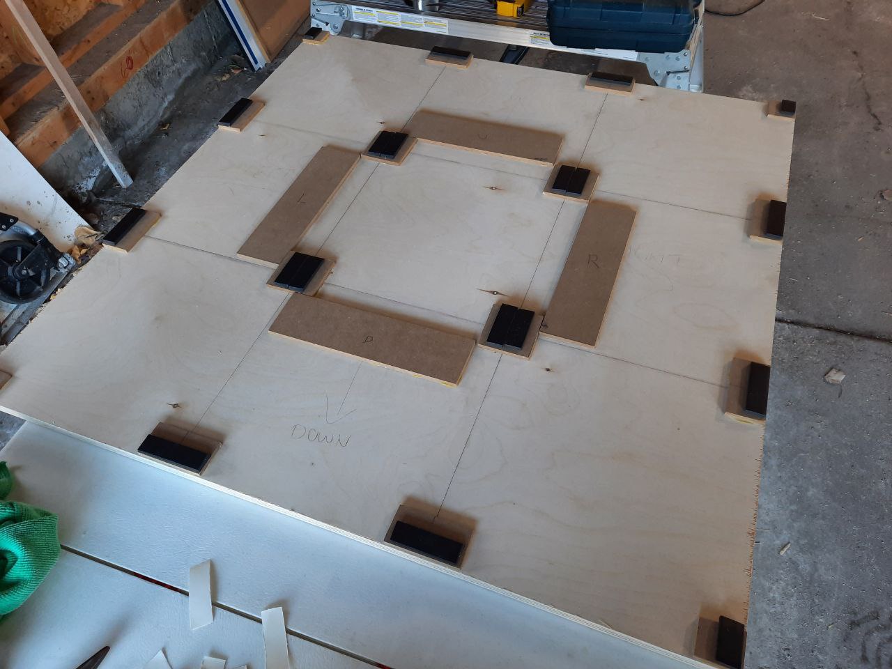
First I measured out and drew outlines for all the panels. Each square drawn on the board is 11"x11". I also cut all the panels, and by I, I mean my neighbour who has a table saw. There was not enough of either the pine or the melamine to make 9 panels of each, so I decided to make 8 melamine panels and 1 pine. In hindsight I'd rather do the exact opposite, with 1 melamine panel in the centre. I (actually me this time) then cut strips of the 1/4" hobby board for the panel supports and FSR mounts and wood glued them in place, pressing them under a bunch of heavy stuff to set overnight. Once it was all dry, I cut and placed the weather stripping on top of the panel supports.
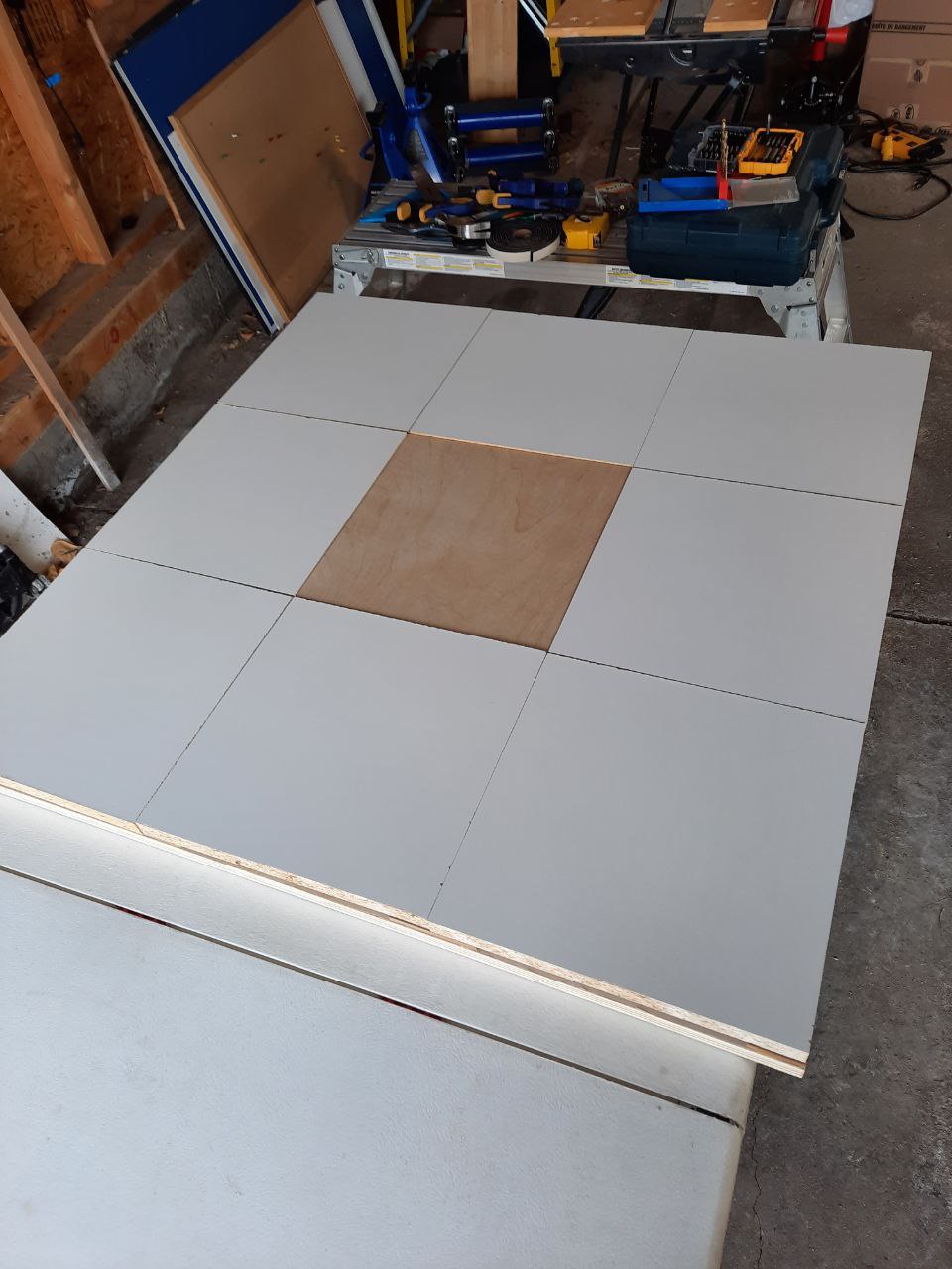
I put the cut panels on top of the base board to check the fit. The panels weren't perfectly square because as it turns out cutting 9 foot long boards with any precision on a table saw is very difficult. That's okay though, it only ever amounted to minor aesthetic issues, no functional problems. Once I was happy with how all the panels sat, I marked the underside of each panel with which one it was supposed to be and in which orientation. Clamping each panel in place, one at a time, I drilled a pilot hole about 1" squared from the corner down through to the base board, followed by a small hole just a bit less thick than the wood screws I would be using. Sorry, I didn't write down the drill sizes I used, but I'm extremely new to doing anything handy and it still worked out great for me, so just use your best judgment.
Next I drilled wider holes, just slightly wider than the screw threads, only down through the panel, so the panel could travel vertically. Since I don't own a countersink bit, I then used a huge drill about the width of the screw head to drill down just a bit on the top of the panel. I wasn't very scientific about this and the end result is fine, so again just use your best judgment. Finally I slowly drilled in the screws until they were just below the top surface of the panel. Unclamping the panel after repeating this for each corner let the rubber decompress, giving the end result of the screw head about 5mm below the top of the panel.
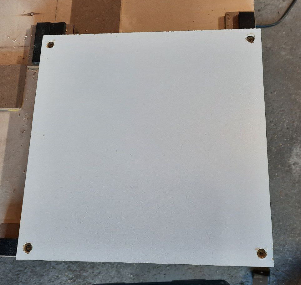
Repeat for all panels. Take breaks and drink water unlike me.
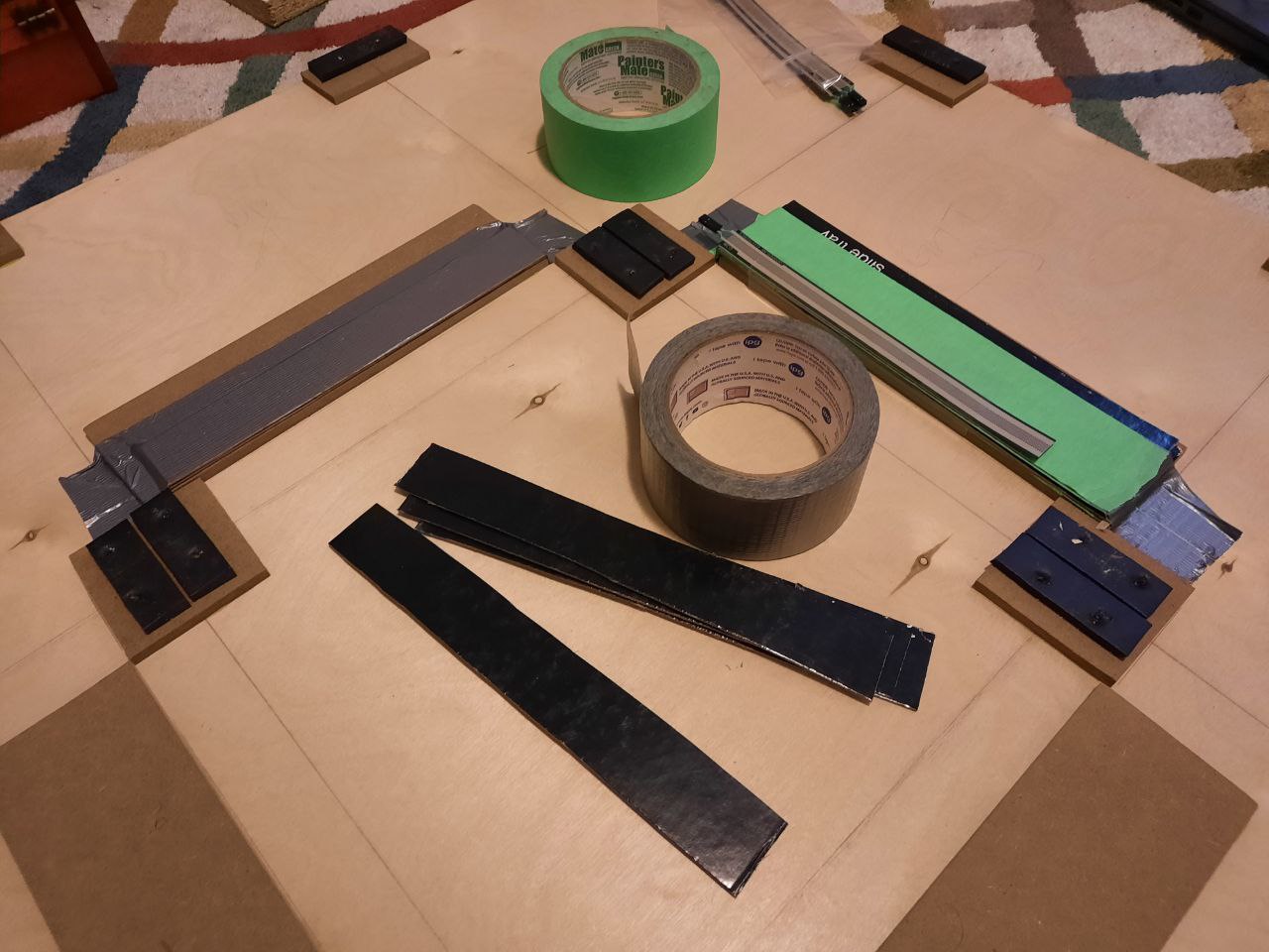
With all the panels done, it's time to start The Good Stuff. After testing one panel for a while I found that the FSRs needed to be much higher than I anticipated. I placed two layers of very thick cardstock on the FSR mount, duct taped them in place, then placed many (many) more layers of painter's tape on top. The FSR is secured in place with packing tape. Other folks use double-sided tape which is probably much better, but packing tape has been adequate. Start with less painter's tape and add it slowly, testing the FSR with a prototype circuit on your breadboard. I used the circuit explained in this video. Again I used 470Ω resistors, but anything you have in the 300 to 1000 range will probably work. I dunno 1000Ω sounds like it'd be too sensitive to me, YMMV. For testing, use any suite mentioned in Sereni's guide.
Anyway! Keep testing the FSRs with the panels just resting in place, adding 1 or 2 layers of painter's tape at a time, until the FSR lies just slightly under the panel at rest. Ideally a very light step should register, but your pressure readings should return to ~0 immediately after stepping off. Try standing with most of your weight on one foot over the panel as if you're inputting a long hold, then step off and see how the pressure readings respond. Test it again after screwing the panel in place with all screws to make sure it doesn't suddenly behave differently.
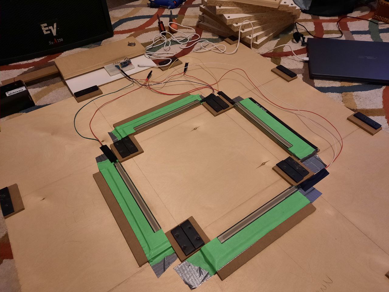
Wire up all the FSRs to make testing a lot easier for you. Here is my final circuit on the breadboard, with a circuit diagram:
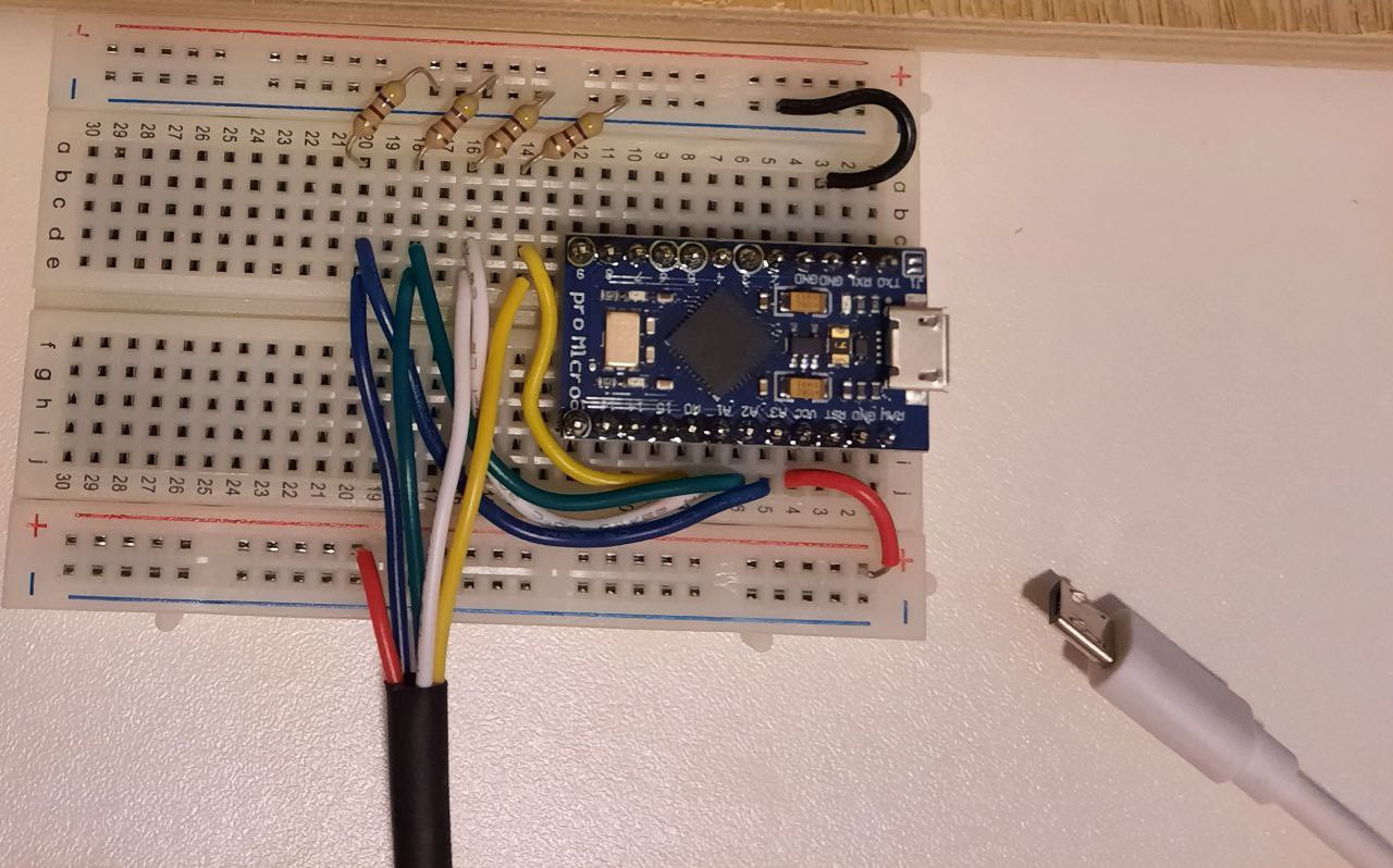
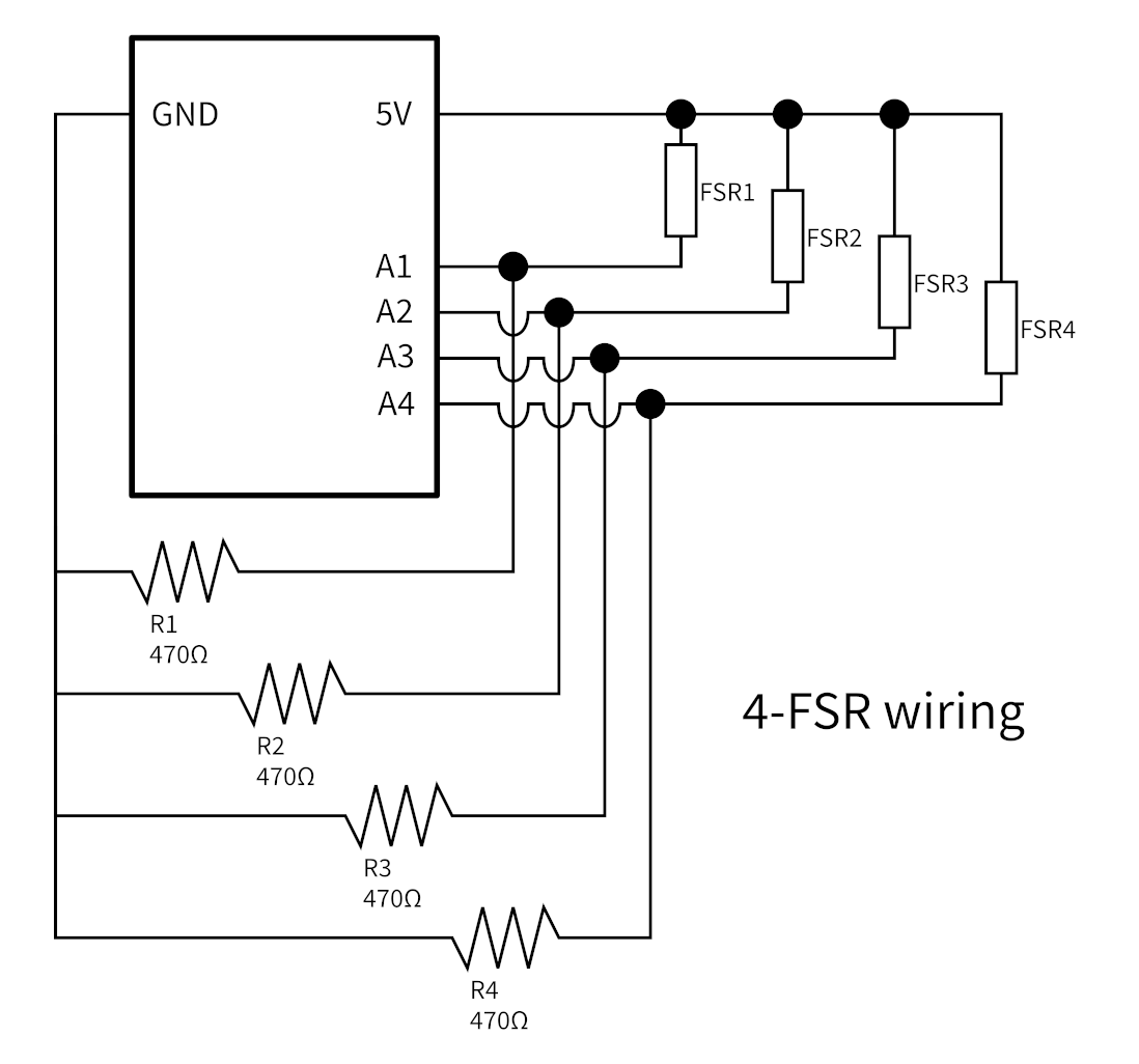
Note that the Pro Micro has 9 analogue pins, so I can later upgrade the pad to 9 panel. BOY HOWDY I do not look forward to redoing that circuitry. Also, here's how the FSRs are wired up:
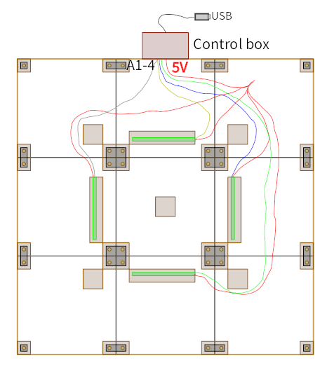
An aside on using DDRPad.com's Arduino Micro clone: You'll get more information about it by searching SparkFun Pro Micro, which is what it's actually a clone of. Any FSR guide you will find will probably only mention this exact microcontroller in passing, and there's one very important extra step you'll need when setting up the Arduino IDE: installing SparkFun boards. SparkFun's website has instructions for Windows, Mac, and Linux. The DDRPad.com Pro Micro clone is 5V/16MHz, so be careful to select that version of the board in the IDE before trying to upload your code to the board.
As a final note on this, if you're using teejusb's FSR suite for programming your board, at the time of writing thresholds are not stored on the chip. All thresholds default to 1000 when you plug the board into a setup, so you won't be able to try the pad on a different computer right away. There are two ways to remedy this. The easy way is to add code that sets the thresholds after initializing the sensors: in the setup() function, after the for loop where the sensors are initialized, add 4 lines of kSensors[?].UpdateThreshold(###);, replacing ? with 0 through 3 and ### with whatever threshold you found best by tooling with the web UI. Uploading this code to your board will make your pad work without the Arduino IDE or web UI open, meaning you can take it to your dedicated setup.
The second way to solve this problem is by implementing the code in this pull request up through commit a1b0b67, which adds a button in the web UI to save your thresholds to your board's EEPROM (memory) chip. Read the full pull request conversation, it's still a work in progress and you should not expect a seamless experience.
The secret third way is to contribute to the repository to help get that pull request merged. I like to think I will do this but I don't know if I'm experienced enough to be useful!
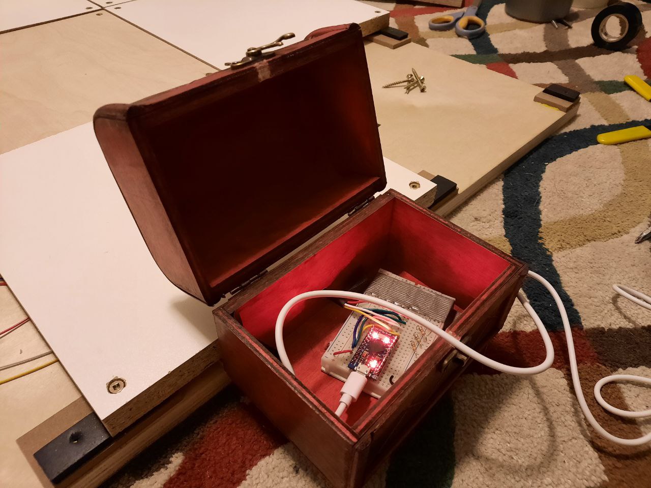
Last step before screwing all panels in place is to make the control box. I picked up this cute box from a thrift store, which is perfect for its extra room to store the USB cable and the latch to keep it closed.
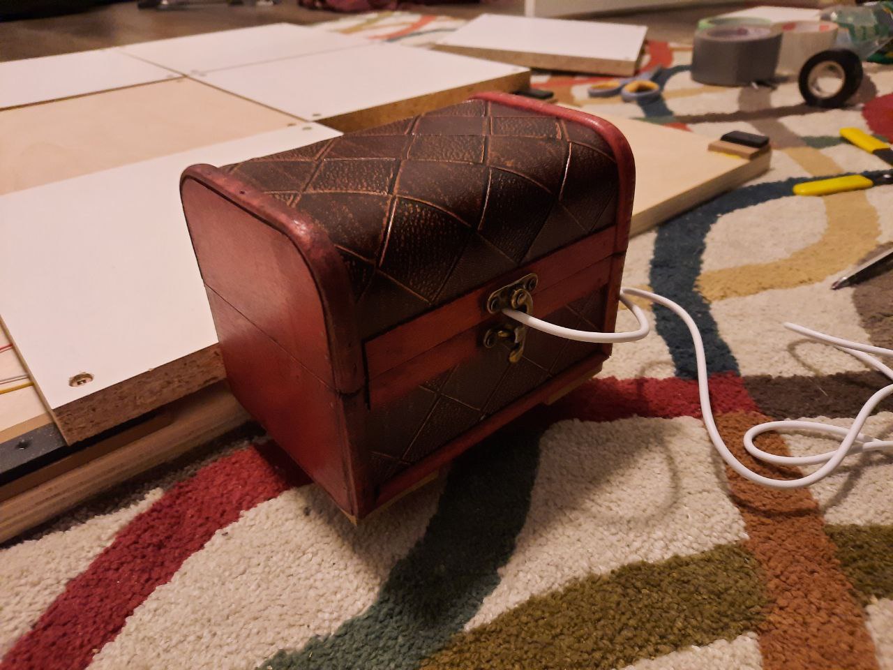
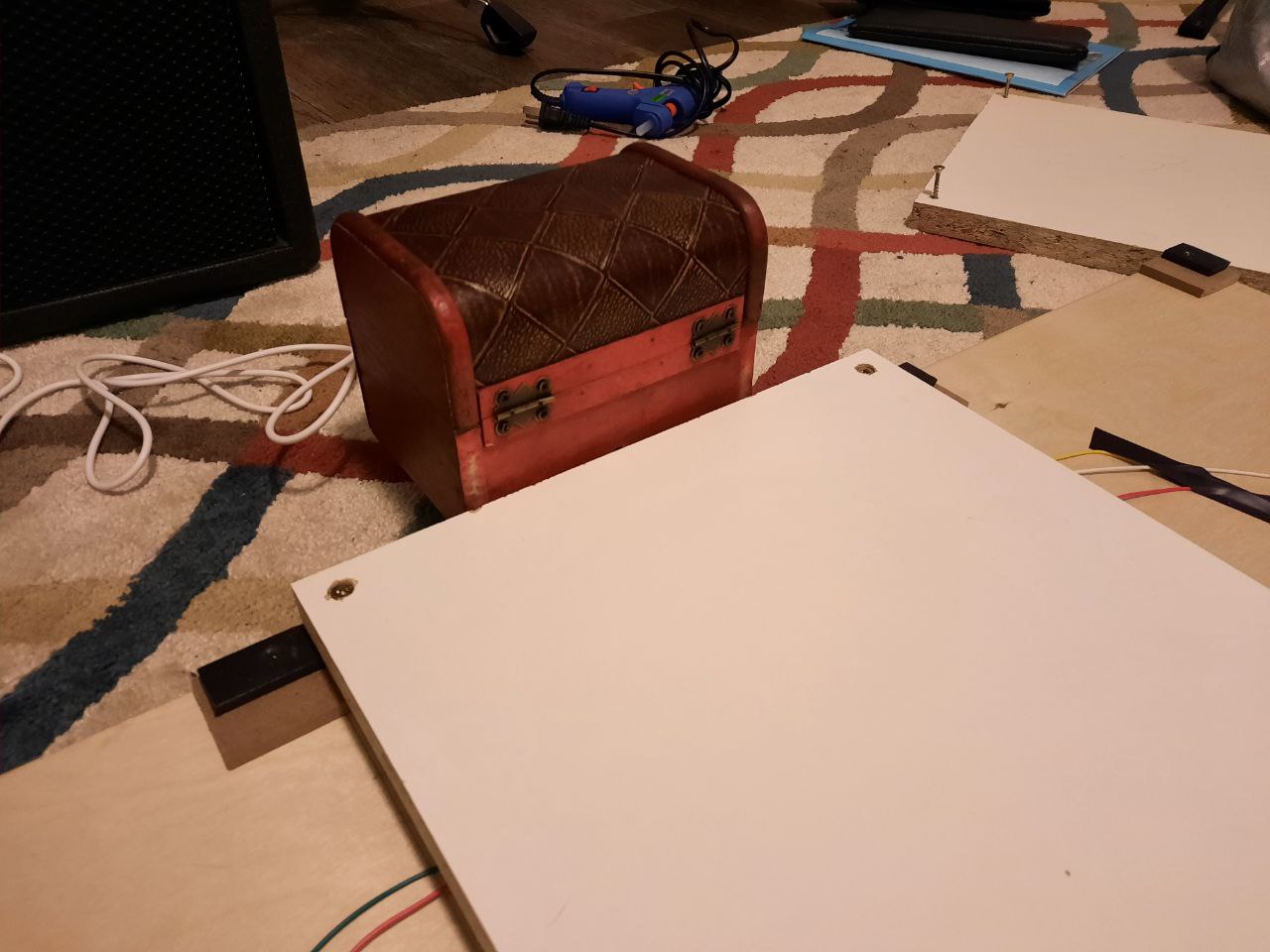
I drilled a hole in the back of the control box to feed the wires through, and also one in the front between the conveniently curved metal clasp so the USB cable could come through while the box is closed. I love this little box so much.
I didn't spend any time actually designing how the control box was going to stay with the pad, so I very much slapped this solution together, but I like the end result. I used two spare long pieces of the 1/4" hobby board, wood glued them to the bottom of the control box, then screwed the long ends of the hobby boards in place onto the base board with some spare 1" screws. If you follow this strategy, just make sure your screws are extremely low height, lower than the panel when fully squished down. Another option is something complicated with a serial connection coming out of the main pad which would then plug into a port installed in the back of the control box, like old home pads used to do. For that to work you'd have to be clever about managing strain on the serial cable so you don't dislodge any of your FSR wiring. That would be bad.
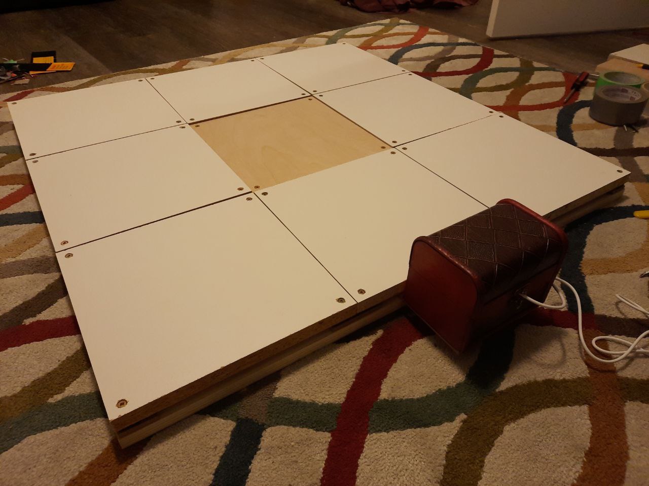
Anyway! That's a dance pad! I stuck some non-slip foam pads to the bottom and started stress testing it. I've been playing with it for about a week since finishing the build and I've been pretty happy with it for how scrappy it is. I've had to remove panels very frequently to tinker with FSR height, along with reflashing the board several times per session as I try different FSR activation thresholds. This will probably be much less painful if your development setup is the same as your ITG setup. I've also since raised the height of the centre panel by duct taping discarded books underneath it, because as you can see the centre panel is actually slightly below the others at rest (the melamine panels are closer to 7/8" thick). I like my pad to be as flush as possible, but the centre panel is raised ever so slightly just so my feet can navigate the pad without me having to look down. I have no idea how I'm going to navigate this whenever I decide to make the other 5 panels have sensors.
One issue worth discussing is the up arrow getting stuck. In gameplay I often had problems with the up arrow retriggering and twitching when I wasn't touching it, and at the same time not triggering at all when I did step on it. After debugging, I've narrowed it down to the panel itself getting stuck partially pressed down after heavy use. Watching the web UI shows that while the up arrow sensor starts around 0 when fresh, it gradually increases its baseline pressure as I play; the more intense the chart, the higher the baseline shifts. This eventually turns into its baseline pressure roughly matching the threshold, causing it to trigger at seemingly random, and also be already above the threshold when I try to step on it. My best guess that the screws are biting into the panel while it is depressed, preventing it from coming back up. So far I've been able to ""solve"" this issue by removing the screws closest to the centre panel. This issue also started to happen on the down arrow and the same strategy alleviated the problem there too. Maybe a more sustainable fix would be redrilling some of the screw holes to be slightly wider, perhaps just the near-centre ones. Not sure.
Otherwise I haven't found much else yet that I'd change for next time. Perhaps a trim around the sides to make it look nicer? My next goal though is to figure out how I might make a DIY bar that can come apart from the pad for storage, because the chair back I've been using is not comfortable.
Thanks
This pad is great for a first DIY project. I owe my success to several people in the ITG community, others on the vast wilderness of the internet, and of course my father-in-law.
So many thanks to the many DIY guides I referenced and variously stole from to cobble together this monster:
- Building a dance pad with FSR and Arduino - Sereni
- Teejusb's FSR Guide
- FSR pad guide - u/johnboyjr29
- Inexpensive Hard DDR/Stepmania Dance Pad Controller - JarrodB1
- Building a DIY Dance Dance Revolution - Melanie Huang
- Making an FSR dance pad from scratch - Dom ITG
Also huge shoutouts to all the folks working together to build software, repositories, videos, etc. for FSRs and DIY pads. The ITG community is really impressive, and I'm excited to get into the game more.
If you decide to build a pad based on this design, I'd be shocked honoured! Please share photos and, inevitably, improvements, with me if you're inclined to. You can find me in the ITL Discord.